Team Members:
- Liam Deck
- Justin Hammond
Project Purpose:
A frame of 1 ½ inch ANSI pipe made of a rigid and practical material must be built to satisfy the dimensions of the engine mounts. The connections between the engine mounts and firewall must maintain predetermined angles, dimensions and locations. This frame must be able to hold minimal displacement under excessive stress of 6 downward G’s and 3 upwards G’s, with no breaking points or excessive elasticity. The material selected must have practical ability to work in the situation, no flammable or non-temperature resilient materials may be used despite lack of direction contact with the engine. A stress test must be performed on the frame and result in a low stress/displacement outcome.
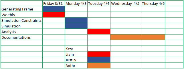
Gantt chart:
Procedure:
- Select each channel in the frame generator.
- Set the channel geometry to 1 ½ ANSI pipe of any wall thickness.
- Select Mild Steel as material.
- Create the course frame draft.
- Extend each frame channel by 2-3 inches in both directions.
- For firewall mounts without intersecting channels, cut each channel to the face.
- For mounting points with intersecting channels, miter each channel to every other channel, with a miter gap of 0mm.
- After mitering each intersecting channel, cut each channel to their intersecting face.
- Finish frame.
- Select Frame Analysis tab.
- Set gravity in the appropriate direction.
- Create fixed constraints on each firewall connection points, pinned connections will allow rotation of the center engine mount, and will not give accurate data.
- For the downward 6 G’s test, place a force of 500 lbforce’s downwards on each of the joints where the engine mount supports meet.
- For the upward 3 G’s test, place a force of 250 lbforce’s upwards on each of the joints where the engine mount supports meet.
- Click simulate.
- Inspect the stress scale on the left.
- If any part of the frame is under too much displacement, inspect the constraints parameters or replace the channel with a stronger metal.
Team Members Responsibility's:
- Liam: Weebly, technical report
- Justin: Inventor, technical report
Solution:
During this project we tested to see how weight was distributed along the engine frame. To test how the weight was distributed we made the assumption that 1/3 of the engine would be resting on the engine frame with the force of gravity pushing it down. When we tested the frame We also tested to see which material was the best for us to use when building this design. We decided to use wrought steel in this design, as it is a good material to use when you need a strong and sturdy frame. Wrought steel can also handle a lot compression forces acting on it, which is very important when it is high up in the air, as it has to deal with low pressure trying to compress the frame. Wrought steels main downside is its weight. Steel is known to be a very heavy material, which is why it is not used that much when building an airplane.
