Project Overview:

The purpose of this project was to create a circuit that displays the creators date of birth. For my circuit it displayed my birthday which is 06-18-00.
Truth Table:
This is my truth table for the 7 segment display we made. The purpose of truth tables is to represent the inputs and outputs for my circuit using 1 or 0 to say if any of the parts are on.
My truth table went from a-g with w, y, and z. The a-g section represents all of the segments in the display. You enter in 1's and 0's to say if that segment is on or off. The last two rows are x's because they don't matter. Then once you have entered the 1 and 0 for a-g you read down each letter vertically. once you have done that for all of the rows you enter it into k maps.
K Mapping:

K-mapping is the easiest way to simplify logic equations as it doesn't require the use of Boolean Algebra. K maps use grouping to determine a equation that says when W ,Y ,and Z are on or off. The numbers have to be entered into the k map in a specific order to get the right equation.
Muiltisim implementation:
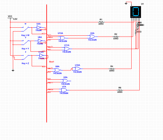
I made my multisim circuit useing a bus format. I did this as it makes my screen a lot less clumped together Because segments D,E, and F are all the same equation I had them all connecting to the same wire. I decided to use my nand logic segment A, I used nand logic for segment A as it was the easiest one for me to figure out to convert it to nand logic. By doing this it made me use another chip so I would say that using a nand chip there was actually counterproductive to saving money. This circuit would require 2 AND chips, 1 NAND chip, 1 inverter chip and 1 OR chip. The seven segment display that we were forced to use was a common cathode, so it is grounded and if positive i works. If the display was common anode, the display would be hooked up to a power source and would work when grounded.
Bill of Materials:

Bread-boarding
The wiring section for this project I found to be one of the easiest parts of the project. I found it a lot easier then it was for the majority vote project.I learned how to better understand which gates are the input and outputs to plug the wires into. The main issues I ran into was that I forgot to ground my a-g segments and I misplaced a wire connected to my nand chip.
Conclusion:
This project taught me how to create a circuit for a seven segment display. During this project the part that I struggled with the most was the k mapping, which is arguably the easiest part of this project. Although I struggled with k mapping I have to say that I am thankful it exists as it made alleviated us from having to find the equations for each segment using Boolean Algebra. Overall I think this project was helpfull to understanding seven segment display circuits.
